Hello all, I got a recent interest in pi and bought a pi3.
I bought a 5'' screen, but it seems the screen needs most of the GPIO pins. The screen fixates on the board on 4 long screws and then the two are connected through a small HDMI-HDMI.
I have two questions:
1. How can I make a case for this setup? I don't want to damage the boards, and sweat or greasy fingers on running circuits doesn't sound right.
2. How can I use the remaining GPIO if the screen takes most of them? I have a ribbon cable for the pins, but that one is kind of useless now since the screen is using them.
-
clytemnestra
- Posts: 45
- Joined: Thu Oct 06, 2016 9:44 pm
Re: Screen using GPIO pins
Hi and welcome to the forum.
Looks like you bought the wrong display. Some designs have a GPIO pass-through connector for adding additional hardware. Otherwise you'll need to use some kind of adapter to 'break into' the cable path. You'll also need to establish with signals your particular display uses - almost certainly the SPI bus pins, plus perhaps 2 or 3 other general GPIO signals.
Texy
Various male/female 40- and 26-way GPIO header for sale here ( IDEAL FOR YOUR PiZero ):
https://www.raspberrypi.org/forums/viewtopic.php?f=93&t=147682#p971555
https://www.raspberrypi.org/forums/viewtopic.php?f=93&t=147682#p971555
-
clytemnestra
- Posts: 45
- Joined: Thu Oct 06, 2016 9:44 pm
Re: Screen using GPIO pins
Wrong? Should I return it? The screen I bought is this one
I wanted to use the PI for GPIOs but to also have a screen for it for easiness.
Note I'm a beginner, I can't really understand "You'll also need to establish with signals your particular display uses - almost certainly the SPI bus pins, plus perhaps 2 or 3 other general GPIO signals."
I wanted to use the PI for GPIOs but to also have a screen for it for easiness.
Note I'm a beginner, I can't really understand "You'll also need to establish with signals your particular display uses - almost certainly the SPI bus pins, plus perhaps 2 or 3 other general GPIO signals."
Re: Screen using GPIO pins
Well maybe not 'wrong' , but it isn't ideal if you need to access the unused GPIO pins - which you do.
So we can see from the link that it is using the HDMI port for video but the Pi's SPI bus for the touch screen (the SPI bus is part of the GPIO port).
It does also have a table of which GPIO pins are unused for the display, so you can tell which other GPIO pins are free for your other hardware.
However it isn't going to be very easy to access the GPIO pins. IMHO I would choose a different display....
Texy
Various male/female 40- and 26-way GPIO header for sale here ( IDEAL FOR YOUR PiZero ):
https://www.raspberrypi.org/forums/viewtopic.php?f=93&t=147682#p971555
https://www.raspberrypi.org/forums/viewtopic.php?f=93&t=147682#p971555
Re: Screen using GPIO pins
Cases are good, help to protect your pi. Some people make their own wooden, plastic or metal cases, others buy premade cases and modify them as desired.
This table from the page you linked tells which GPIO's the touchscreen uses, the NC pins are not connected and so are free for other use.
The screen you have chosen gets it video signal from the HDMI connection, it uses the GPIO header for the touchscreen feedback. If you don't wish to use the touchscreen function then just using a longer HDMI cable will solve your issue.clytemnestra wrote:Wrong? Should I return it? The screen I bought is this one
I wanted to use the PI for GPIOs but to also have a screen for it for easiness.
Note I'm a beginner, I can't really understand "You'll also need to establish with signals your particular display uses - almost certainly the SPI bus pins, plus perhaps 2 or 3 other general GPIO signals."
This table from the page you linked tells which GPIO's the touchscreen uses, the NC pins are not connected and so are free for other use.
SPI is Serial Peripheral interface, a communications method between devices (in this case the touchscreen and the pi) some of these pins can be shared by multiple SPI devices if needed. The screen needs to use at most 8 of the GPIO pins, 6 of which will still be able to be used by other devices for the same purpose.PIN NO. SYMBOL DESCRIPTION
1, 17 3.3V Power positive (3.3V power input)
2, 4 5V Power positive (5V power input)
3, 5, 7, 8, 10, 11, 12, 13, 15, 16, 18, 24 NC NC
6, 9, 14, 20, 25 GND Ground
19 TP_SI SPI data input of Touch Panel
21 TP_SO SPI data output of Touch Panel
22 TP_IRQ Touch Panel interrupt, low level while the Touch Panel detects touching
23 TP_SCK SPI clock of Touch Panel
26 TP_CS Touch Panel chip selection, low active
Doug.
Building Management Systems Engineer.
Building Management Systems Engineer.
Re: Screen using GPIO pins
Thanks Doug. The problem is getting access to the unused GPIO lines - the display board will still need power via the GPIO port.BMS Doug wrote: The screen you have chosen gets it video signal from the HDMI connection, it uses the GPIO header for the touchscreen feedback. If you don't wish to use the touchscreen function then just using a longer HDMI cable will solve your issue.
Texy
Various male/female 40- and 26-way GPIO header for sale here ( IDEAL FOR YOUR PiZero ):
https://www.raspberrypi.org/forums/viewtopic.php?f=93&t=147682#p971555
https://www.raspberrypi.org/forums/viewtopic.php?f=93&t=147682#p971555
Re: Screen using GPIO pins
texy wrote:Thanks Doug. The problem is getting access to the unused GPIO lines - the display board will still need power via the GPIO port.BMS Doug wrote: The screen you have chosen gets it video signal from the HDMI connection, it uses the GPIO header for the touchscreen feedback. If you don't wish to use the touchscreen function then just using a longer HDMI cable will solve your issue.
Texy
I would probably use a short ribbon cable with an extra connector.
Doug.
Building Management Systems Engineer.
Building Management Systems Engineer.
-
clytemnestra
- Posts: 45
- Joined: Thu Oct 06, 2016 9:44 pm
Re: Screen using GPIO pins
The screen can be placed in the GPIO slot and it will take both touchscreen and power from there OR HDMI and microUSB (it also works plugged in one of the pi's USBs, but not sure how much power it will take).
The problem with HDMI is that I don't know how to fixate it, because I have to place the screen somehow on the table, and it might damage it. The part where I place it in the GPIO is kind of keeping the screen and pi tied together.
Touch screen is also quite convenient to use, too. Will the used GPIOs affect my ability to properly use the pi for projects?
Another problem is that I can't really find other screens except the 3 or the 7 inch ones, but I thought 7 is not worth to buy since 5 is enough and it's at half the price of the 7 one.
Re: Screen using GPIO pins
That depends entirely with the hardware you want to connect to. So your touchscreen uses the SPI bus, OK only 1 channel, but it more or less rules out those SPT specific pins for any additional hardware. What do you have in mind?clytemnestra wrote: Will the used GPIOs affect my ability to properly use the pi for projects?
Texy
Various male/female 40- and 26-way GPIO header for sale here ( IDEAL FOR YOUR PiZero ):
https://www.raspberrypi.org/forums/viewtopic.php?f=93&t=147682#p971555
https://www.raspberrypi.org/forums/viewtopic.php?f=93&t=147682#p971555
-
clytemnestra
- Posts: 45
- Joined: Thu Oct 06, 2016 9:44 pm
Re: Screen using GPIO pins
That's the problem, I don't know yet what I want to do 
First off, I'll do the LED circuit and a button one, then I want to make something more practical around the house, will see. All in due time, but I'd like to use the screen since it seems more practical (and I wasted money on it).
First off, I'll do the LED circuit and a button one, then I want to make something more practical around the house, will see. All in due time, but I'd like to use the screen since it seems more practical (and I wasted money on it).
-
clytemnestra
- Posts: 45
- Joined: Thu Oct 06, 2016 9:44 pm
Re: Screen using GPIO pins
So can I still use it for small projects with the remaining GPIO?
Re: Screen using GPIO pins
Yes of course.
Various male/female 40- and 26-way GPIO header for sale here ( IDEAL FOR YOUR PiZero ):
https://www.raspberrypi.org/forums/viewtopic.php?f=93&t=147682#p971555
https://www.raspberrypi.org/forums/viewtopic.php?f=93&t=147682#p971555
-
clytemnestra
- Posts: 45
- Joined: Thu Oct 06, 2016 9:44 pm
Re: Screen using GPIO pins
What ability will it mostly hinder? Does it take anything important?
I found a 3D printing service in my town and don't want to spend the money if I'm going to be needing the other pins, too. Can't afford two cases, either.
Sorry for all the dumb questions.
I found a 3D printing service in my town and don't want to spend the money if I'm going to be needing the other pins, too. Can't afford two cases, either.
Sorry for all the dumb questions.
Re: Screen using GPIO pins
Yes, the 5v and 3v3 connections will be inaccessable under the connection.clytemnestra wrote:What ability will it mostly hinder? Does it take anything important?
I found a 3D printing service in my town and don't want to spend the money if I'm going to be needing the other pins, too. Can't afford two cases, either.
Sorry for all the dumb questions.
If you are custom designing the case allow some seperation between the pi and the display and use a short 40 pin ribbon cable with an extra male connection for the screen. (You will need to split the ribbon after wire 26 to use this connector)
Doug.
Building Management Systems Engineer.
Building Management Systems Engineer.
-
clytemnestra
- Posts: 45
- Joined: Thu Oct 06, 2016 9:44 pm
Re: Screen using GPIO pins
I will also need an HDMI-HDMI, too it seems.
What's the difference between simply connecting them and using cables? Aren't I using the same pins for both the connection and the 26-pin male one?
What's the difference between simply connecting them and using cables? Aren't I using the same pins for both the connection and the 26-pin male one?
Re: Screen using GPIO pins
The additional connector on the ribbon cable will give you access to the gpio pins for other uses.clytemnestra wrote:I will also need an HDMI-HDMI, too it seems.
What's the difference between simply connecting them and using cables? Aren't I using the same pins for both the connection and the 26-pin male one?
Doug.
Building Management Systems Engineer.
Building Management Systems Engineer.
-
clytemnestra
- Posts: 45
- Joined: Thu Oct 06, 2016 9:44 pm
Re: Screen using GPIO pins
I got a cable with 3 female(pcie cable). Would that work if I can get a male-male and connect the screen to one of it?
Re: Screen using GPIO pins
If that is a cable for connecting PC hard drives to the motherboard make sure it does NOT have 80 wires. (40 wires for the 40 contacts in the female connectors and 40 for grounds between them to reduce cross-coupling.) Connecting one of those to a RPi will kill the RPi.clytemnestra wrote:I got a cable with 3 female(pcie cable). Would that work if I can get a male-male and connect the screen to one of it?
Quis custodiet ipsos custodes?
-
mikronauts

- Posts: 2823
- Joined: Sat Jan 05, 2013 7:28 pm
Re: Screen using GPIO pins
Put a board (with stacking connectors) between the Pi and the LCD add-on.
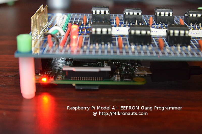
Pic above is one of my large prototyping boards connected to an Raspberry Pi A+ with a stacking header - it would be easy to plug one of the GPIO based LCD board on top of it.
I used a 40 pin tall stacking header with two spacers for my prototyping board.
Proto board: http://www.mikronauts.com/proto/ezaspieproto300/
Article pic came from: http://www.mikronauts.com/raspberry-pi/ ... rogrammer/
texy wrote:Thanks Doug. The problem is getting access to the unused GPIO lines - the display board will still need power via the GPIO port.BMS Doug wrote: The screen you have chosen gets it video signal from the HDMI connection, it uses the GPIO header for the touchscreen feedback. If you don't wish to use the touchscreen function then just using a longer HDMI cable will solve your issue.
Texy
http://Mikronauts.com - home of EZasPi, RoboPi, Pi Rtc Dio and Pi Jumper @Mikronauts on Twitter
Advanced Robotics, I/O expansion and prototyping boards for the Raspberry Pi
Advanced Robotics, I/O expansion and prototyping boards for the Raspberry Pi
Re: Screen using GPIO pins
That is a good solution for a permanent build, i got the impression that the OP wanted to be using solderless breadboard for messing about with I/O.mikronauts wrote:Put a board (with stacking connectors) between the Pi and the LCD add-on.
Pic above is one of my large prototyping boards connected to an Raspberry Pi A+ with a stacking header - it would be easy to plug one of the GPIO based LCD board on top of it.
I used a 40 pin tall stacking header with two spacers for my prototyping board.
Proto board: http://www.mikronauts.com/proto/ezaspieproto300/
Article pic came from: http://www.mikronauts.com/raspberry-pi/ ... rogrammer/
Doug.
Building Management Systems Engineer.
Building Management Systems Engineer.
-
clytemnestra
- Posts: 45
- Joined: Thu Oct 06, 2016 9:44 pm
Re: Screen using GPIO pins
That's what I do. I have a breadboard and want to play with the thing.
So, I have a 40-wires ribbon cable with 3 mother slots. Can I connect one of the mothers to the pi, one to the LCD and the other to the breadboard and have it all working? Just need to find a way for the LCD's mother to connect to the mother of the cable.
How does the pi know that it gets signal from the breadboard and not from the LCD in this case?
Re: Screen using GPIO pins
With the exception of the ground and power pins just make sure each pi Gpio pin is only connected to one device.
For now at least, whilst you are learning.
Texy
For now at least, whilst you are learning.
Texy
Various male/female 40- and 26-way GPIO header for sale here ( IDEAL FOR YOUR PiZero ):
https://www.raspberrypi.org/forums/viewtopic.php?f=93&t=147682#p971555
https://www.raspberrypi.org/forums/viewtopic.php?f=93&t=147682#p971555
-
clytemnestra
- Posts: 45
- Joined: Thu Oct 06, 2016 9:44 pm
Re: Screen using GPIO pins
If I use the ribbon cable with the male for the screen, can I use the 5v and 3v pins used by the screen on the other female end? Will they get power and not interfere with the power taken by the screen?
The problem is the screen came with a small HDMI-HDMI thing that will only fit if the screen and pi are tied together. The alternative would be a HDMI cable, but the shortest I got is 1m length which is way too big.
Why is this so complicated..
The problem is the screen came with a small HDMI-HDMI thing that will only fit if the screen and pi are tied together. The alternative would be a HDMI cable, but the shortest I got is 1m length which is way too big.
Why is this so complicated..
Re: Screen using GPIO pins
clytemnestra wrote:If I use the ribbon cable with the male for the screen, can I use the 5v and 3v pins used by the screen on the other female end? Will they get power and not interfere with the power taken by the screen?
Yes, that will be fine.
0.3m hdmi cables can be had fairly cheaply.clytemnestra wrote: The problem is the screen came with a small HDMI-HDMI thing that will only fit if the screen and pi are tied together. The alternative would be a HDMI cable, but the shortest I got is 1m length which is way too big.
Sorry about that, hopefully it will all be worth it in the end.clytemnestra wrote:Why is this so complicated..
Doug.
Building Management Systems Engineer.
Building Management Systems Engineer.